The archives of the Institution of Civil Engineers (ICE) contain the longitudinal section of the Liverpool & Manchester Railway (L&MR) used by Thomas Telford in his report to the Exchequer when the L&MR attempted to release the final tranche of its funding. On his recent visit to London Paul of the L&MR Trust digitised and reconstructed the section into a single enhanced image file.
I thought it would be interesting to render this in 3D using OpenSim so resized the image and then split it into 18 pieces and used these to texture 18 14x14 m panels mapped roughly onto a CC BY-NC-SA licensed 2D map of Lancashire from University of Manchester Archives. The 30-odd miles from the Mersey to Salford (the original intended terminus) were thus condensed into a virtual wall some 252 virtual metres in length.
I then adjusted the virtual terrain so that it followed the course denoted by the red line on the section (discussed below) except where embankments were to be constructed in which case red-shaded prims were added to show these.
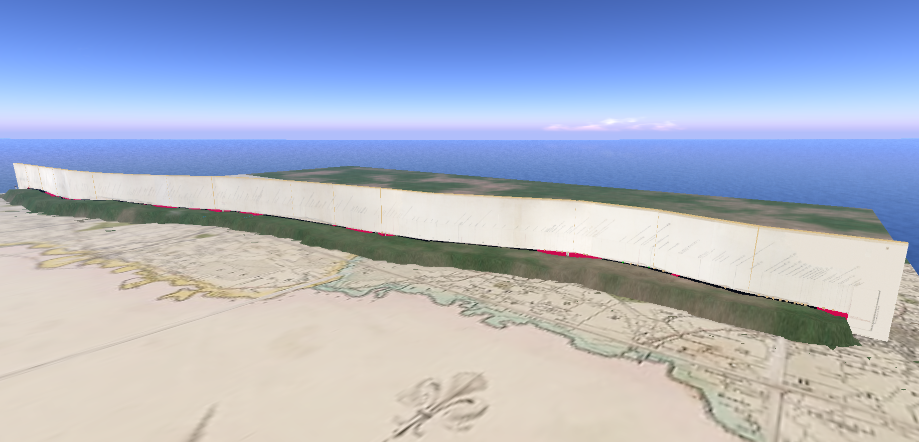
Fig: General view of the OpenSim display which spans the breadth of a single region. The track is displayed at the foot of the vertical panels, either in black or, for embankments and bridges, in red.
The origin of the section
According to Thomas (1980), Telford's assistant, James Mills, found that the only section available in Liverpool during his inspection in December 1828 was the one drawn up by CB Vignoles for the Rennies in 1825 following Stephenson's dismissal. Mills therefore employed a draughtsman to make the copy now with ICE.
There is an immense amount of data in the section but I have no specialist technical knowledge so, as usual, some conjecture…
The Wapping tunnel
The section starts in Liverpool with the ascent of the Wapping tunnel from the goods station near the docks to Edge Hill. The small tunnel to the passenger terminus at Crown Street is not included (carriage of passengers was a secondary consideration) but there are some potentially interesting sidelights on the tunnel construction at that location.
Firstly, there is an air shaft in close proximity to the extant vent so there is support for the commonly supposed notion that a pre-existing shaft formed the basis for the vent.
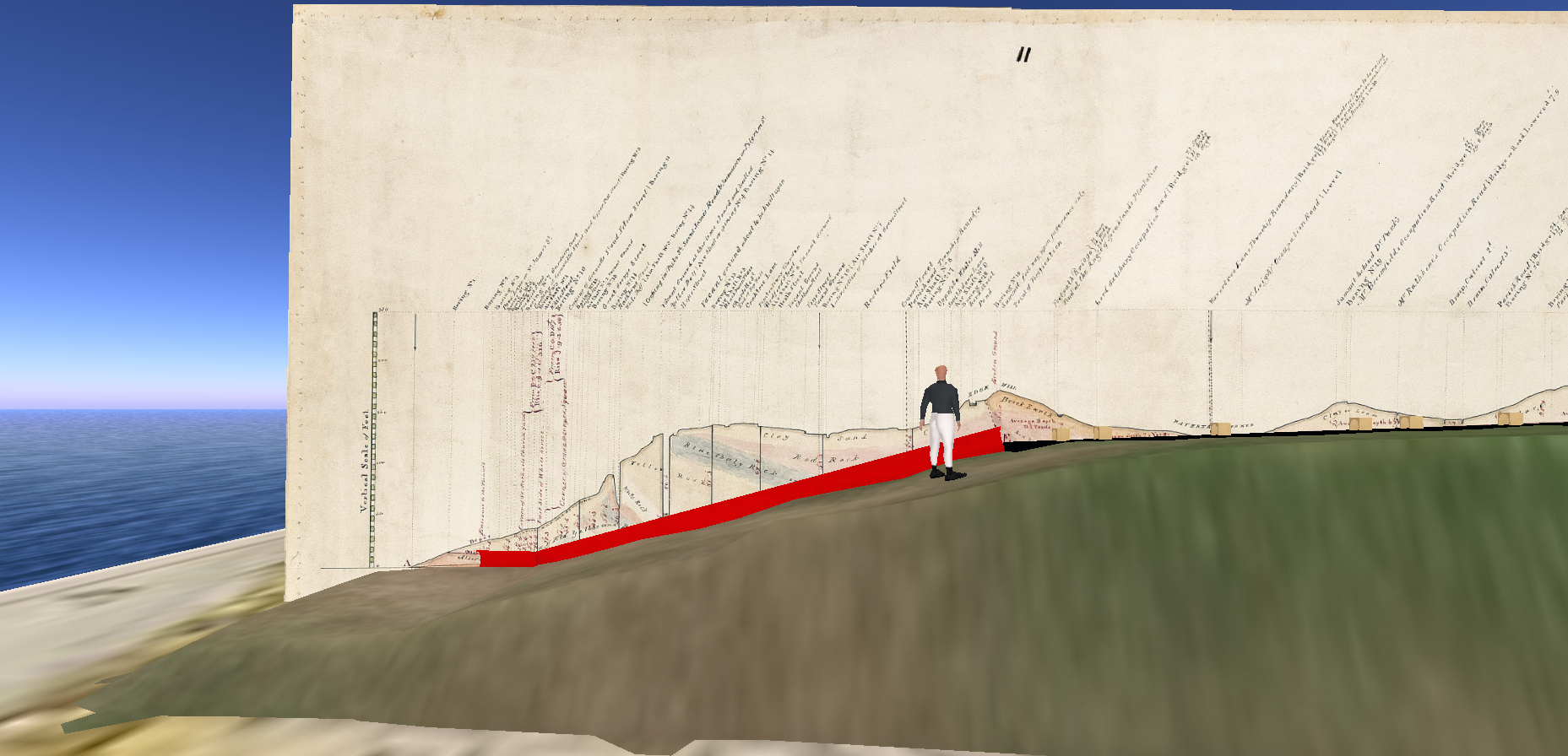
Fig: The ascent of the Wapping tunnel (shown in red). Annotations on the panel above can be seen by manipulating the avatar camera.
However, there is also a "boring" roughly in the middle of the Crown Street field that may have been reused as part of the eye for construction of the tunnel as proposed previously. Note that the majority of borings were presumably carried out for geological purposes prior to construction. The assumption that some were subsequently reused seems reasonable but does not automatically follow. Indeed, the presence of nine air shafts covering the length of the tunnel is in much better agreement with the eight eyes originally put out to contract. The two shafts at Millfield are both specified at 20 feet although the section shows the air vent as 27.5 ft (the adjacent boring is similar) while at Edge Hill ("top of the tunnel") the depth of the boring is in closer agreement (35 ft vs 36 ft in the specification). The section lacks an air shaft at this site, the nearest being east of Smithdown Lane at the top of the current headshunt. Of course, extending the tunnel eastwards would lead into the Chatsworth Street cutting although much of the work there was completed relatively late.
The specification mentions one eye on "vacant ground east of Bedford Street" which presumably equates to an air shaft on the section, both at a depth of about 60 ft. The female penitentiary is also indicated and this is often cited as the location of a drift.
Blackburne Place, the site of a surviving ventilation shaft, is absent from the original specification but the location of both a boring and an air shaft.
In some cases borings and air shafts were in close proximity such as at the White Delf. The section confirms that these were at the level of the bottom of the quarry rather than the adjacent street. In this instance the proximity of the two shafts may have been a response to the limited space available either in a busy quarry or adjacent streets. Alternatively it may have signalled that the site was dual purpose.
Indeed, it is possible that the air shafts are highlighted on the section because they were intended to persist after the remaining sites had been closed up. Although the passage of trains might have been transient, staff would have had to undertake maintenance work on the track and haulage system. We also know from an account by the composer Felix Mendelssohn that staff had fires lit within the tunnel and that the tunnel was lit by gas, both observations supporting the ongoing presence of air shafts. [UPDATED 03/11/2019]
The red route
The section appears to map out two routes through Rainhill, the original (red) mapped by Vignoles and approved in the 1826 Act and an alternative subsequently adopted by the re-appointed Stephenson (black) with support from the Board of Directors but against the advice of the L&MR consulting engineer Josias Jessop.
The red route delivered a more level (and hence operationally cost-effective) railway but required a substantial cutting at Rainhill. The black route on the other hand follows the extant route which was originally to have required stationary engines at the Whiston and Sutton inclined planes which flanked the Rainhill Level. However, the subsequent Rainhill Trials suggested that travelling locomotives would suffice, if necessary either by splitting trains at the inclines or through assistance from a banking engine, i.e. locomotive.
Thomas (1980) suggests that Stephenson's adoption of the inclined planes may have been a strategem to prevent the use of horses for passenger services as specified by the Rennies. Stephenson, of course, had a vested interest in the use of locomotives as well as a profound belief in their being the best option for the future.
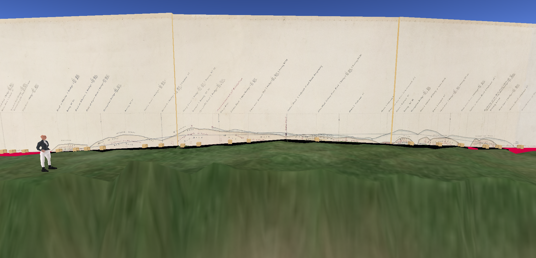
Fig: The track on the display follows the red route favoured by the Rennies. However, the costs of the construction of the huge cutting were such that the black route was adopted as can be seen on the display rising, reaching a level and subsequently falling again.
For the purposes of the display I have used the red route as it is historically interesting and leaves the black route visible above.
Bridges
There are some 91 bridges on the section, both over and under the railway, which are currently represented in the display by bridge icons on the track. Bridges were a significant cost element so it is possible that not all were built if alternative arrangements could be made. On the other hand footbridges were largely omitted from Booth's published list of 63 bridges. One footbridge that features early in the section is visible in the Bury prints of the Moorish Arch.
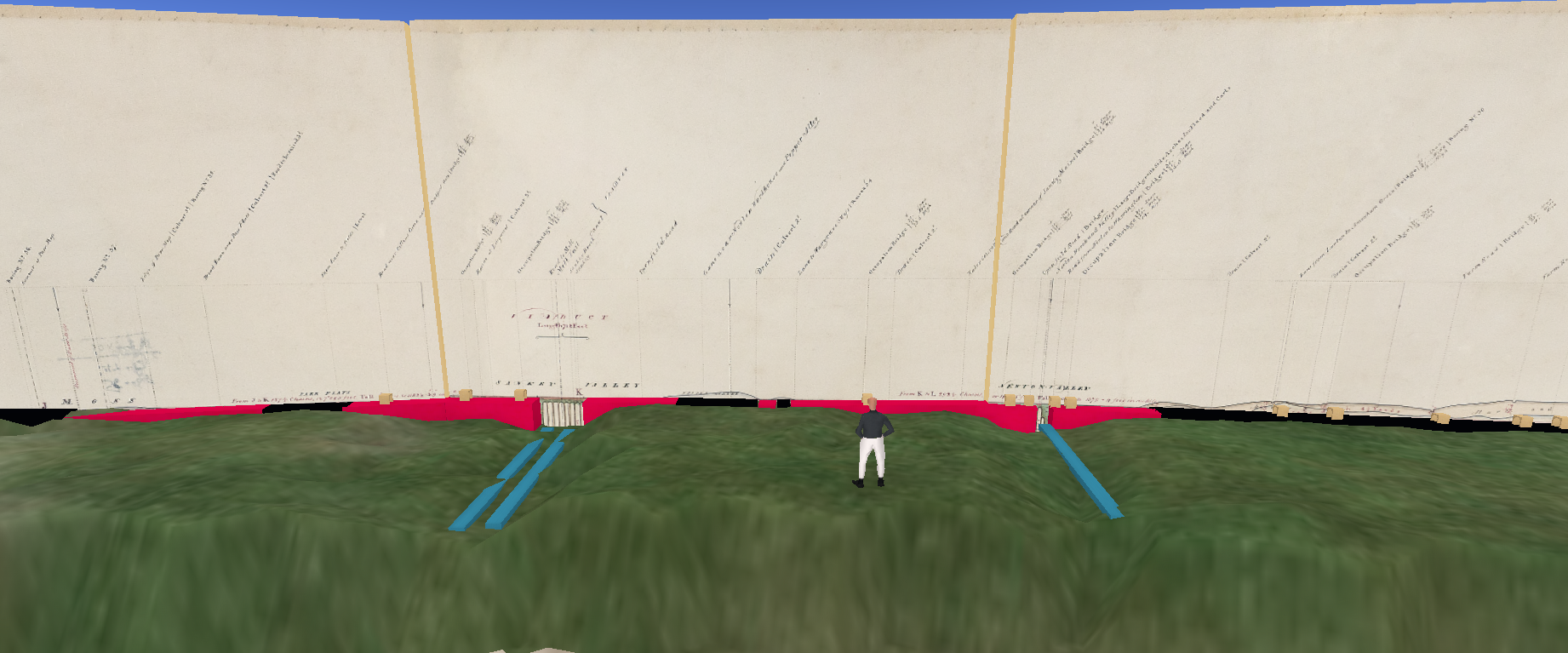
Fig: The embankments are shown in red leading to and from the viaducts as shown on the section for the Sankey valley (only 8 arches!) and at Newton. Note that bridges on the embankments will almost certainly be under-bridges.
Conclusion
The Telford section is a very valuable resource although some care needs to be taken in its interpretation as it represents an intermediate phase in development of the L&MR.
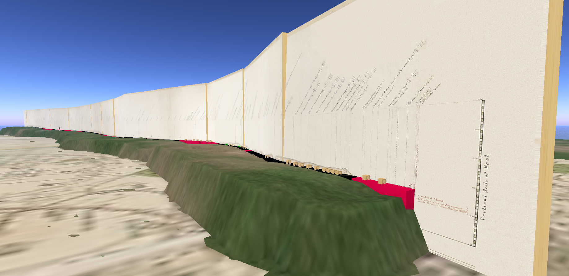
Fig: The section finishes at Salford. Passage across the Irwell and Water Street was a relatively late development.
The OpenSim display was put together in a few hours (terraforming was done manually and thus the principal time sink). The low resolution of the OpenSim terrain was a limiting factor but might be mitigated by building on a larger scale. The ability to program terrain height dynamically makes it feasible to consider simulation of the construction of the railway over time, at least at a gross level.
Acknowledgements
Many thanks to ICE and Paul of the L&MR Trust for access to the section.